6.3 KiB
Graphical Configuration
!!! Warning This page overlaps Configuration. They should be merged to one page!
General remark:
- to activate the changes, currently the device needs a restart after saving the changes.
- partially the commands needs processing on the ESP32 device. This is not very fast - so please be patient.
Access to the graphical user interface
The graphical configuration mode can be reached via the "Edit Configuration" button in the main menu (/index.html):

Overview function
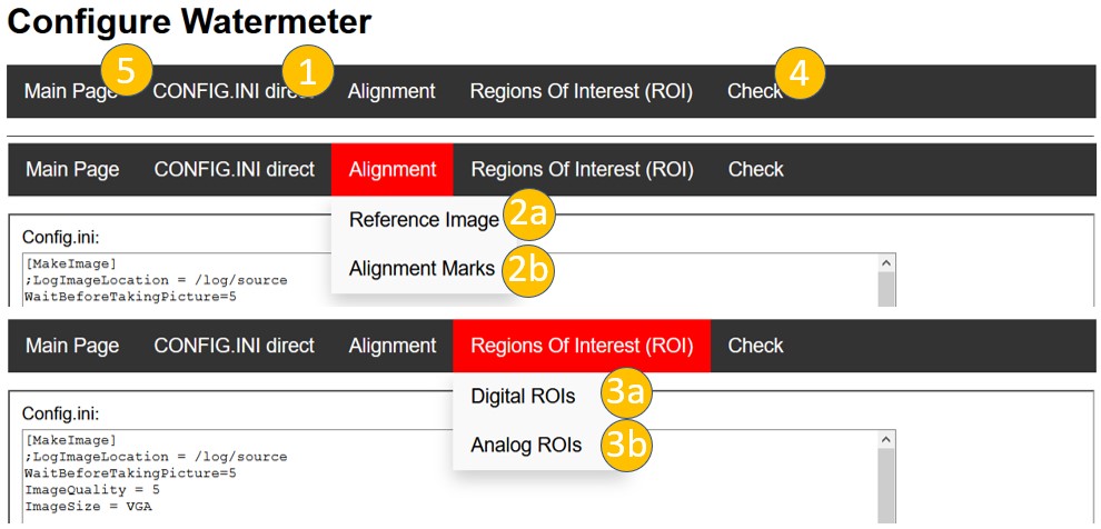
- Direct edit
config.iniin text editor - Configuration of image alignment a. Create of reference image b. Define alignment structures
- Definition of ROIs for digits and analog pointers
- Test the settings
- Back to main menu ("index.html")
1. Edit Config.ini
This is a text editor for the config.ini. Changes committed with the button on the lower left.
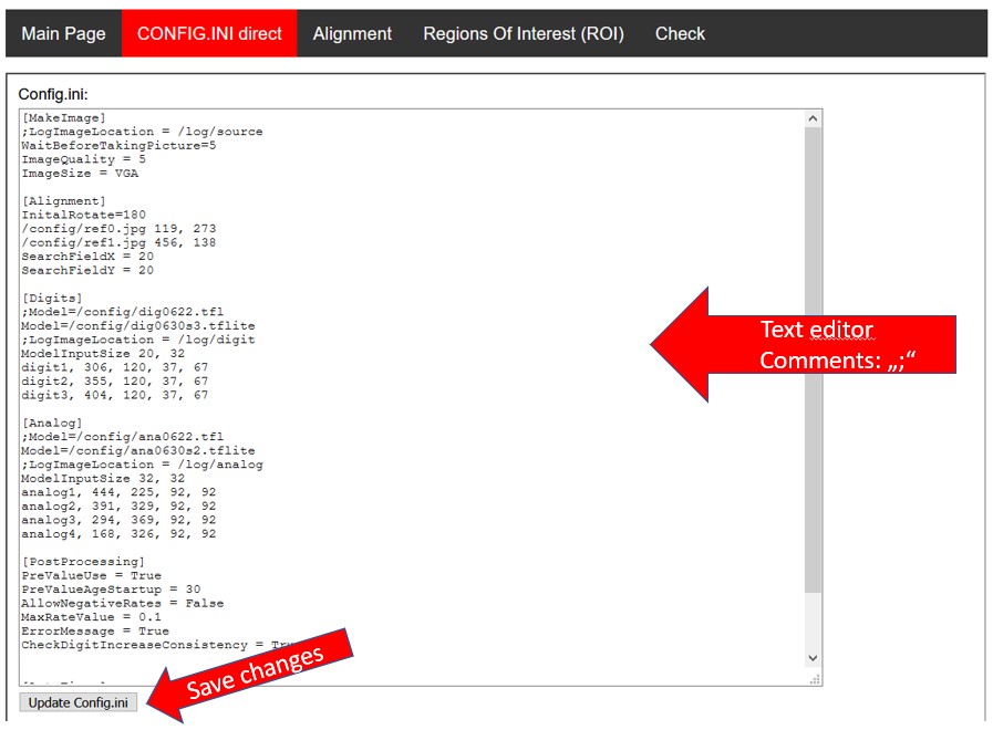
Details see Configuration-Parameter-Details.
2a. Create Reference Image
The reference image is the basis for the coordination of the ROIs. Therefore it is very important, to have a well aligned image, that is not rotated.
‼️ Attention: Updating the reference image, also means, that all alignment images and ROIs needs to be taught again. Therefore do this step only with caution.
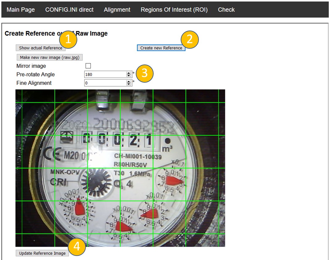
At first the current image is shown and no adjustment is possible. To reload the actual image push the button "Show actual Reference" (1). To define a new reference image push the button "Create new Reference" (2).
Then the last taken raw image from the camera is loaded. If you want to update this, you can push the button "Make new raw image (raw.jpg)". If you need to mirror your image (e.g. mirror before camera) you can do this by selecting "mirror image". After loading the mirroring (in case checked) and the pre-rotation angle from the config.ini are applied. Then use the rough and fine adjustment to get the image straight aligned (3).
If everything is done, you can save the result with "Update Reference Image" (4).
If you have problems with reflections, you can turn the camera in a positions, where the reflection is at a position, where no important information is. To reduce the intensity of the reflection you can also a peace of felt ("Filz") as diffusor at the LED.
2b. Define Alignment References
The alignment references are used to realign every taken image to the reference coordinates. Therefore two alignment structures are identified and the image is shifted and rotated according to their position with the target to be in exactly the same position as the reference image.
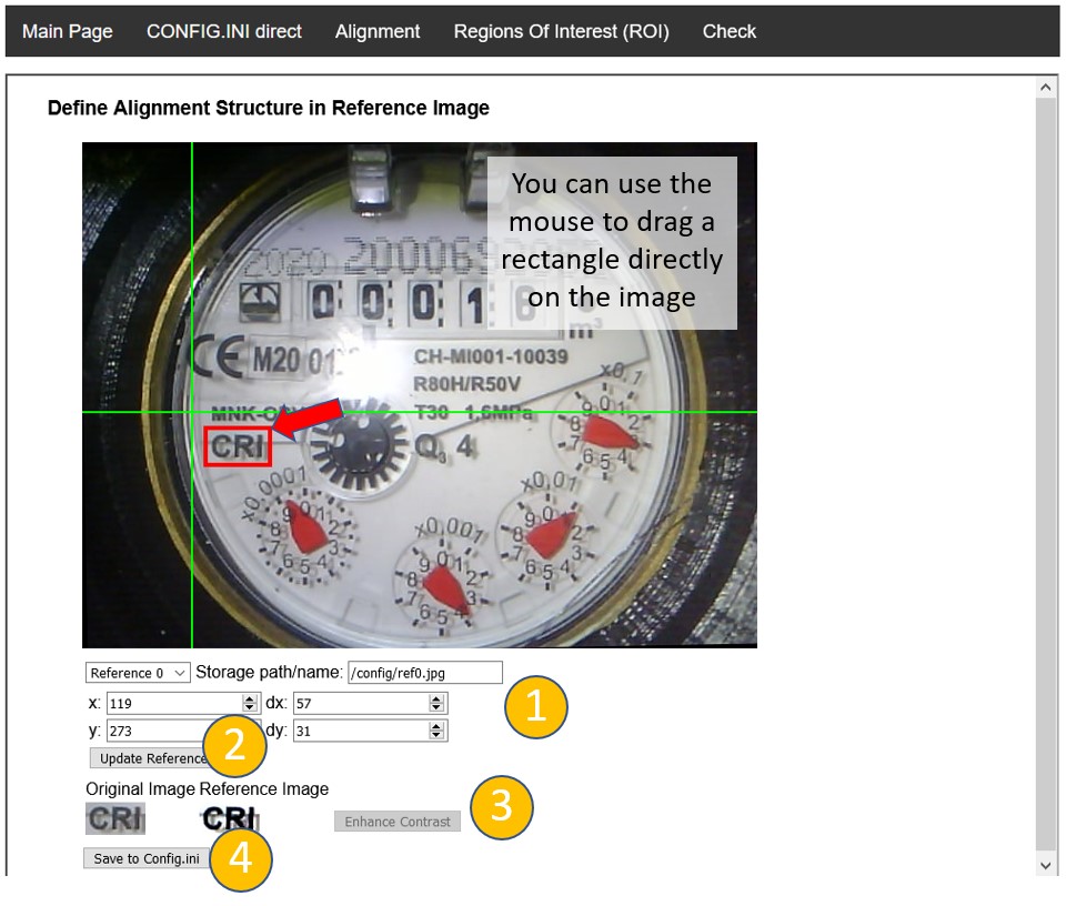
The alignment structures needs to be unique and have a good contrast. As this is the most calculation intensive process, only a field of view of 40x40 pixels around the original coordinates are scanned. This can be adjusted manually in the config.ini(Parameter: SearchFieldX / SearchFieldY).
In the upper part of the settings you can control the position and size of the selected reference image. You can define the ROI in the image directly via drag and drop with the mouse. Go to the starting point, push the left mouse button and drag your ROI. You will a red rectangle with the newly selected position. To make this active, you need to push "Update Reference" (2). You can change between the two reference images with the drop down box ("Reference 0", "Reference 1").
In some cases it might be useful to use a reference with a higher contrast. This can be achieved by pushing "Enhance Contrast" (3). The result will be calculated on the ESP32 - so be a bit patient, before you see it active.
To save the modified reference to the config.inipush finally "Save to config.ini".
3a./3b. Define ROIs for image recognition
Here the regions of interest for the digital and analog pointers are defined. As both are done identically, here as an example the digital images are shown.
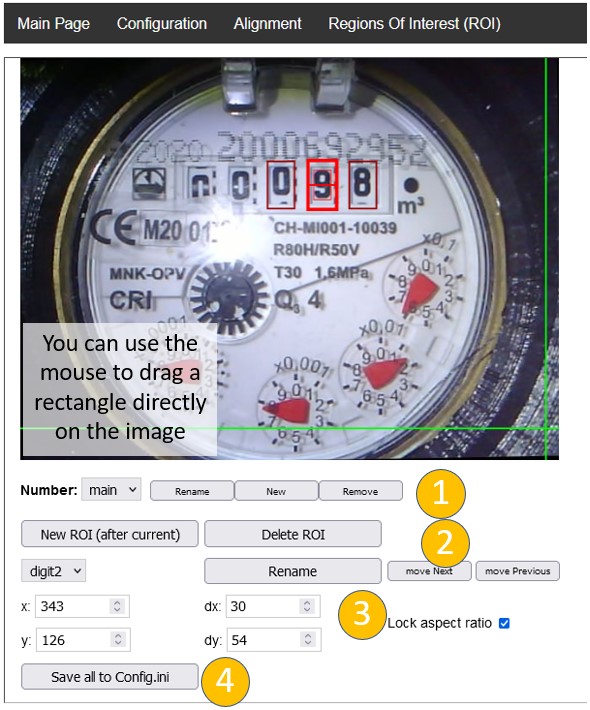
First of all you can define more than one number, for example in a dual meter counter. This can be done with defining a "Number" (1). Analog and digital ROIs belonging to the same "Number" are considered to be part of the same counter.
As for the reference images you can change position, size and name of the ROI in the text fields or define them via drag and drop through the mouse button. You can iterate through the defined ROIs through the drop down box in the left upper area (2). To define new or delete ROIs use the corresponding button. Be careful: if you delete all ROIs, the tool will ask you to define minimum one manually in the config.ini.
The order of the ROIs correspond to the position of the digit / analog pointer in the final readout number. The order can be changed with the button "move Next" / "move Previous" (3).
In order to have a good recognition, the active ROI has two rectangles for alignment:
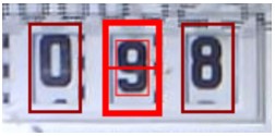
- The outer rectangle is the final size of the ROI
- More important is the inner smaller rectangle. This should tightly fit around the number itself in x- and in y-dimension. Maybe you need to unlock the aspect ratio to change x- and y-size independently
- The line in the middle should go through the middle of the number (in case it is not moving in or out)
To save the result push "Save all to config.ini" (4).
‼️ Attention: Currently you have to reboot the ESP32 to take the changes in the config.ini to take place.
This steps are running on the ESP32 directly. So be patient with the results.